This post was originally on www.instructables.com created by user naessensseppe
DIY Lighter Aid
DIY Lighter Aid in Use
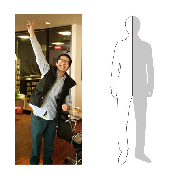
This product is specially made for Nicole. Nicole is a woman that loves atmosphere and coziness in her apartment. An important element is that she loves to light candles.
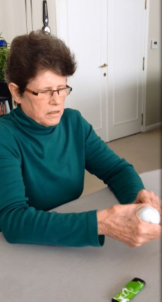
Currently she performs the operation of lighting candles with a lighter rod. As a result of osteoarthritis in her hands she has to use both hand to do this, for her, painfull operation. This is not an efficient operation and requires a lot of strength and agility . Moreover, this is very stressful for her body .
Nicole lives alone in her apartment and can not always count on the help of others.What Nicole wants is bringing coziness in her apartment by light independently and in a simple way light her candles.Thanks to the lighter aid this desire was fulfilled and Nicole is having a lot less problems.
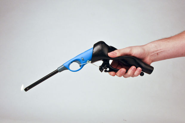
The lighter ais has been fixed to an existing lighter rod in order to bring the advantages of both object together. The additional benefits of the aid are the thickened grip with a customized thumb support and the easy operation of the lighter by squeezing the hand.
Thanks to the lighter ais is is possible for Nicole to operate the lighter with one hand and with a limited force. There is already a simple security presence on the lighter so that is poses no danger to the grandchildren but that is still manageable for Nicole. Moreover Nicole preserves the length of the lighter, so that candles in a deep vase can be reached.
TEAM:
Client: Nicole
Design team: Seppe Naessens, Ward Declerq
Occupational therapist: Kjenta Furniere
Step 1: Gather your materials and tools
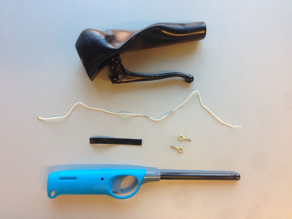
Materials
Plasticine or clay
Lighter rod
2 component casting silicone with stiffnes A30
5 pieces wood
Low density polyutherane foam
Braided polyamide rope (rope with little stretch)
2 Eyebolts
Putty
Bicycle brake lever
Paint
Tools
Drill
Sandpaper
Step 2: Personal Handprint
Personal Handprint
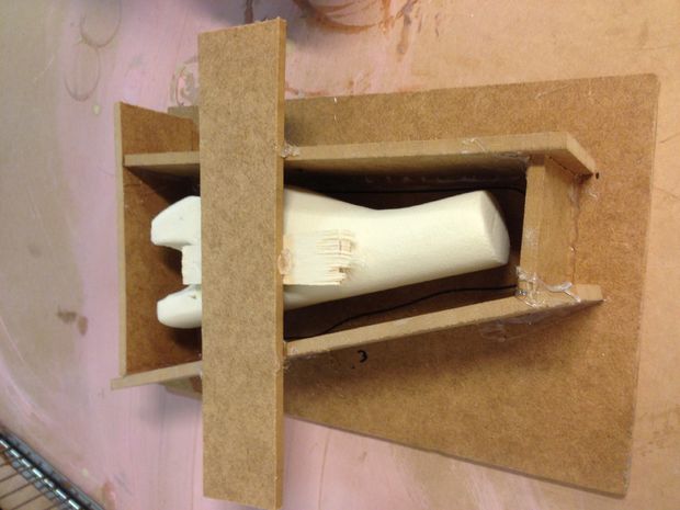
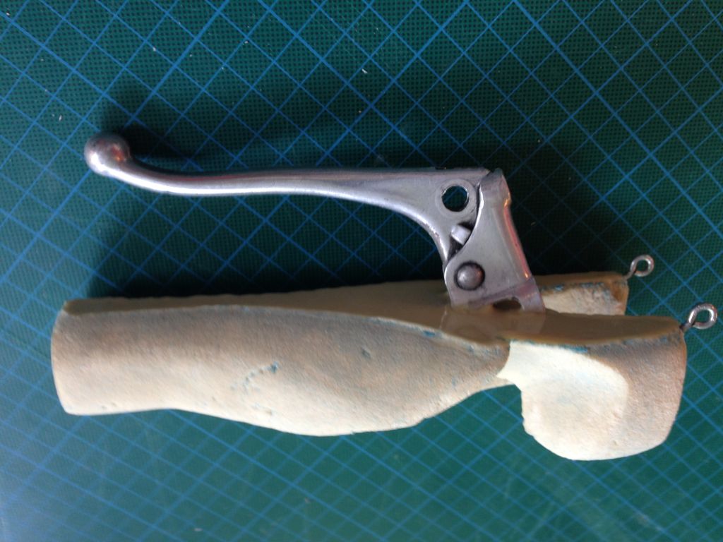
Use the plasticine or clay to make a handprint of the person who will use the lighter aid.
Model it so it looks like a handgrip. In our case and with special attention to Nicole’s condition we had to support the thumb as much as possible.
We tested this shape with ad foam model (because plasticine was too weak to support the thumb). But if you use clay you don’t need to make this foam model, because clay is strong enough to support essential parts of the hand.
Make a hole where your specific lighter rod can clamp in.
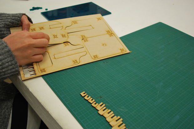
Step 3: Make silicone mold
Making the Mold
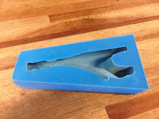
Use the 6 pieces of wood to make a mold. Make the mold as small as possible so you need a minimum of silicone.
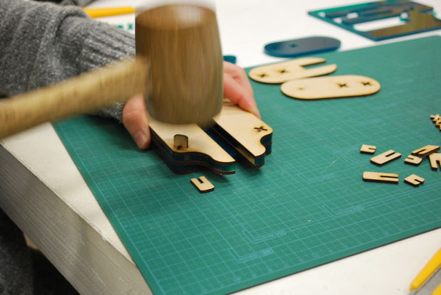
Glue the handprinted silicone of clay model on the woodpiece on top. than will the mold with silicone untill the model is almost fully under. Let the silicone cure for 3hours.
Get the model out of the silicone. Most likely the model has to be broken to get it out.
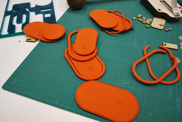
Step 4: Casting
Casting
Casting Complete
First spray the inside of the mold with release wax to get the model easely out of the mold.
Fill the silicone mold with foam. Let the foam cure for a while. During the curing you have to embed the bicycle brake into the foam. So the brake is attached to the model.
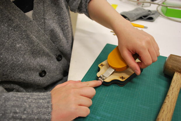
Step 5: Finish model
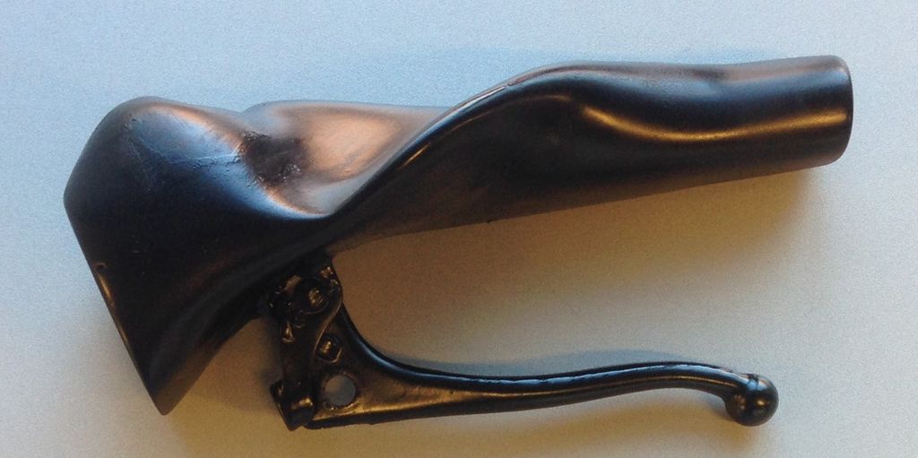
Finished Product
Sand the model to get a clear and good surface. Paint it in a color your client desires.
This post was originally on www.instructables.com created by user XenonJohn
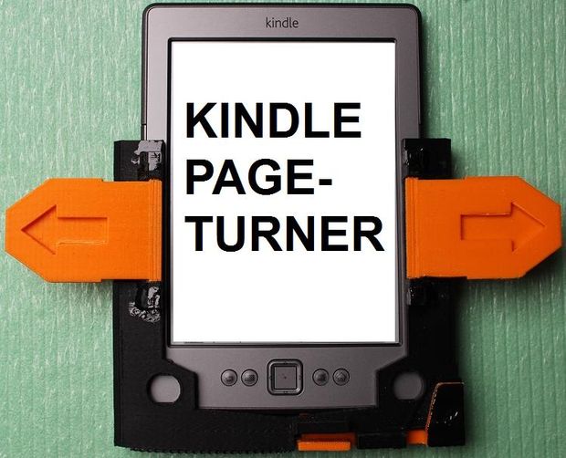
Page Turner
Mechanical page turner for the Kindle in case of weakness or hand tremor………….
This is a simple device that allows anyone with co-ordination impairment, muscle weakness or hand tremor to turn the pages more easily on a Kindle e-reader, using flat levers or tabs each side.
Kindles are made by Amazon and are a form of electronic book. They can store many books in their memory which can be downloaded from the web. The screen is different to that of an i-Pad for example in that it only uses power when turning the page, giving a very long battery life.
They are ideal for use when in hospital.
However, the pages are turned by small thin buttons on the sides, which can be very fiddly for anyone with the slightest co-ordination problem, muscle weakness or hand tremor, i.e. quite a lot of people in hospital.
You might rightly point out that the latest generation Kindles, not shown here, have touch screens that can be set up so if you tap one side of the screen the page will “turn”.
This is true, however I am getting feedback from people with MS for example that tapping the lever each side is still much easier than tapping the screen correctly every time.
Having posted this briefly before, I am posting here the latest variant which has been tweaked a little and also has an enlarged tab which allows you to easily turn it on and off (the power button on the underside is also tiny). I did try to get this made properly by injection moulding via Kickstarter but learned my first crowdfunding lesson: it is not cool, electronic or funky enough for that audience!
I do get asked to make one now and then by people who track me down, so for the good of society, here are some instructions………………3D files are attached to Step 5.
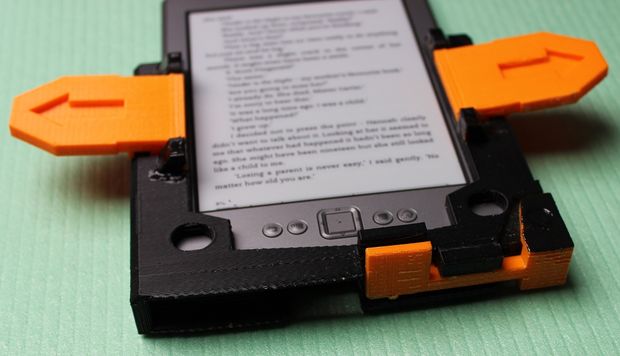
Step 1: How it works
How it works
This photo shows the levers better and particularly the one on the underside which is hinged on the bottom right corner of the device.
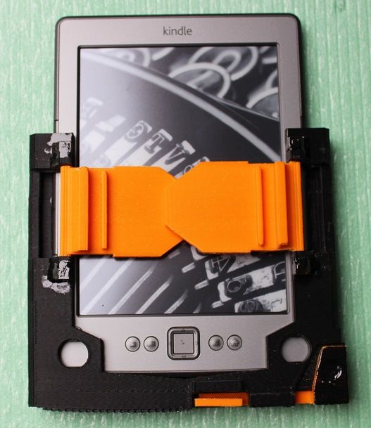
Step 2: How it works (b)
How it works
The levers fold in when not in use (take care not to scratch screen though).
You can see the ridges on undersides of the tabs which press against the long thin page turn buttons on the sides of the Kindle
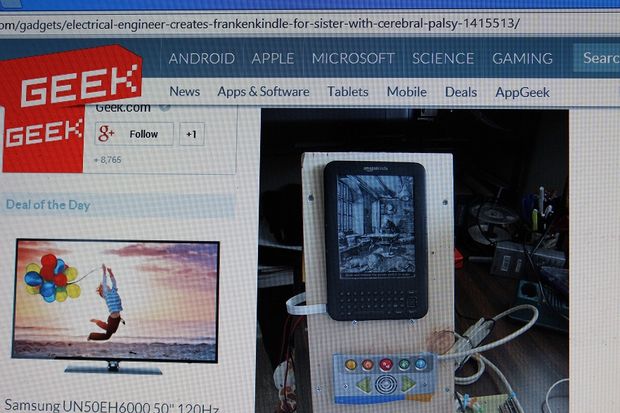
Step 3: Why make it ? (a)
why make it?
Well, here is a project called the FrankenKindle by an engineer attempting to do something similar electronically for a relative with cerebral palsy. It worked but took a lot of Kindle-hacking to get there by the look of it.
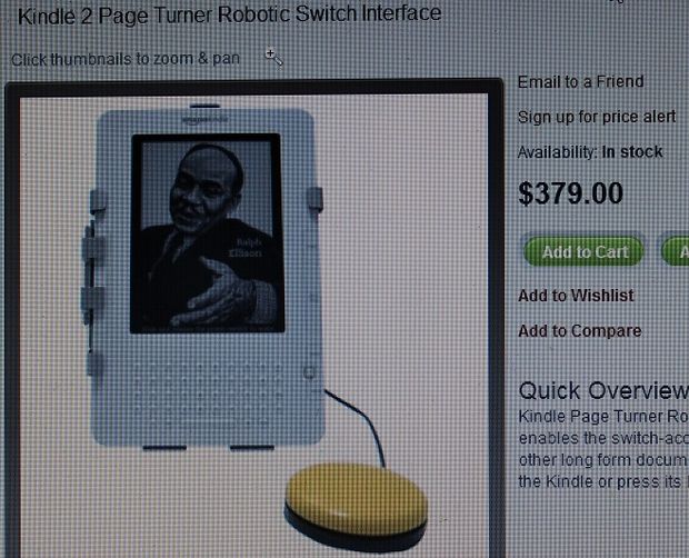
Step 4: Why make it ? (b)
Why make it?
Here is another one with a single button to turn the page. A bargain at just $379.
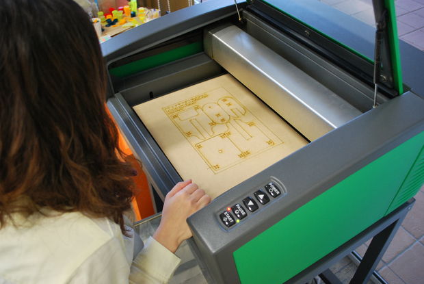
Step 5: Print the parts
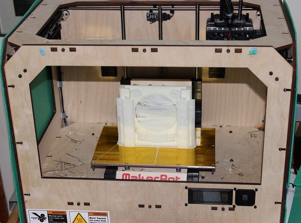
Print the parts
I use a MakerBot Replicator. This is the original plywood one which cost less than half as much as the current post-corporate buyout version.
Files were made on Google Sketchup 8.0 (.skp files) then exported as .stl files for the printer using a plugin.
NOTES ON PRINTING:
a) The hinge pins I print out horizontally, no raft.
b) The levers I print out on one side edge (not flat on print bed else edges curl up). This makes the holes each side nice and strong also.
c) The main body is tricky. I print it from base upwards, i.e. NOT laying flat on print bed else it curves and Kindle will not slide in. I DO use a raft and support for this part. The room is cold this time of year so only way to stop cracking and shrinking was to panel in all sides of machine and use a cardboard box as a top cover. This keeps everything warm inside and stops shrinkage. Earlier versions printed OK in hot summer weather without having to do all this.
I cover print bed with “slurry” method: I dissolve spare ABS plastic shavings in an egg cup of acetone until it forms a thin goo. Smear print bed with this ABS slurry using a cotton bud and things will stick to the Kapton tape.]
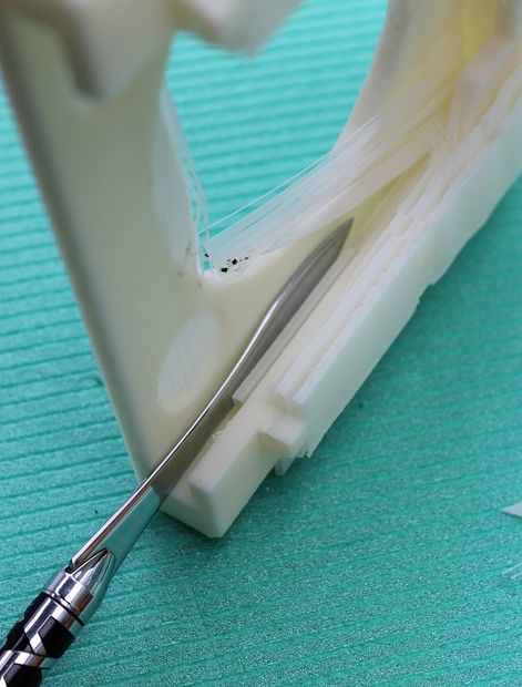
Use file to carefully clean all the dross out of the channels the Kindle will slide down into.
The Kindle will be a firm fit but not really tight else plastic will just crack.
Note: When Kindle inserted you can still insert power lead to charge it without having to take it out of the plastic frame. I have left a hole in underside for the charging lead. This is good as could damage the 3D print sliding the Kindle in and out all the time.
Step 7: Clean up the prints (b)
Clean up the tabs
Clean the tabs especially at sides where hinges will go
Step 8: Clean up the prints (c)
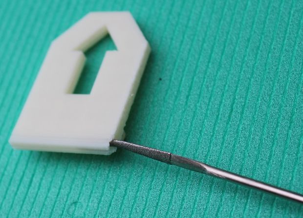
Clean up print edges
This is delicate, use small needle file to clean out holes each side where the hinge pins will go.
Step 9: Assemble the hinges (a)
Assemble the hinges
The hinge pins slide in from each side of the tab. Trial fit everything first, make sure the tabs move freely before you start glueing in the hinge pins. File the pins very slightly if required.
I used to glue them with thick superglue but now I use the ABS slurry again.
Mix spare ABS plastic with acetone, leave it to evaporate a little until is a thick goo. With a cotton bud use it to glue the pins in each side.
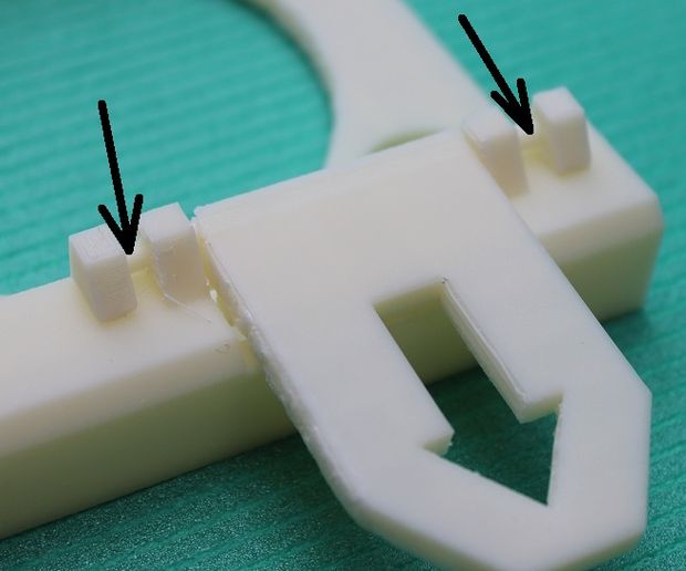
NOTE: The actual pin end that inserts into the tab should have NO glue on it else they will not fold up and down once all is set. Put the slurry/glue where shown by the arrows and do not overdo it. Can always add a little more on surface later on.
Hold pins in correct position until they set. This does not take long. Make sure tab moves freely as things set (very gently).
It is very handy to use a pair of cheap plastic magnifying spectacles or similar when doing all this.
Step 10: Assemble the hinges (b)
Assemble the hinges
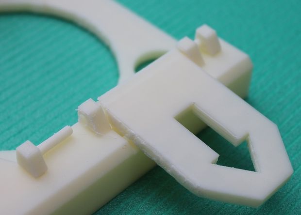
This shows how the parts are meant to go together to form the tab hinges.
Step 11: Assemble the hinges (c)
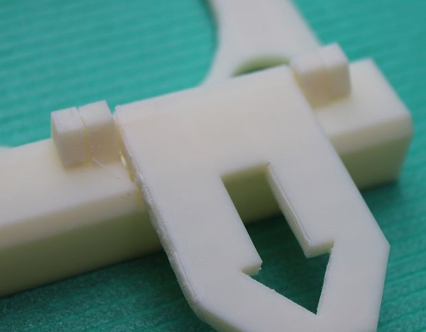
Assembled Hinges
Here they are assembled and glued into position.
Step 12: Hinges finished
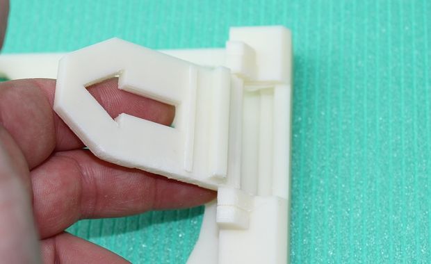
Finished Hinges
The hinged tabs should move freely else it will not work!
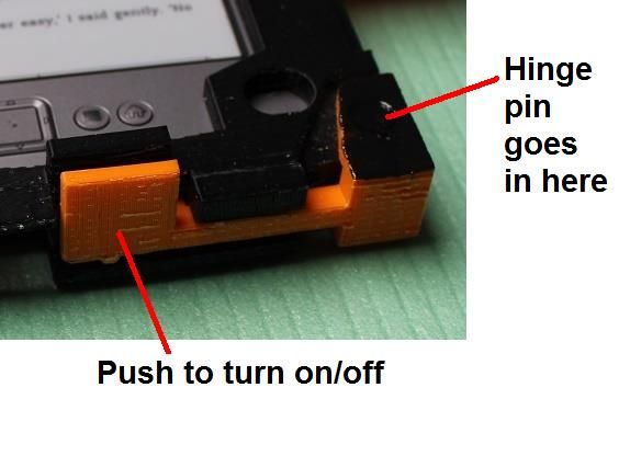
Step 13: Assemble the big power on/off button on underside
Assemble the power button
This is a new improved addition to the design. Pressing the tab puts pressure on the tiny power on/off button on underside of the Kindle. File it carefully until it just fits nicely. Once you have printed it out you will see how it goes together.
The tab on underside in orange is hinged on the right. A large round pin is pushed through main frame and secured with small dab of slurry/glue, once all holes have been filed out, cleaned up carefully and everything trial fitted first.
If you do not need this feature then just do not bother fitting it.
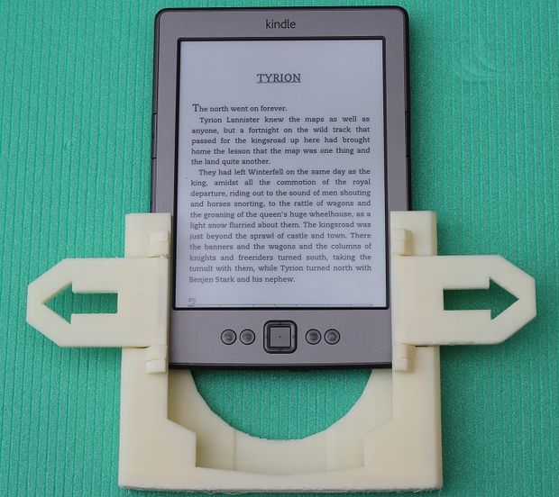
Step 14: Slide in Kindle and you are ready to go
Slide in the Kindle
Slide in the Kindle.
It should be a firm fit but do not force it else the printed plastic will crack. Check you have filed out any printer debris from the guide channels on each side.
You should then be ready to go.
If you use a Kindle in bed a useful addition is a pyramid shaped cushion to go on your lap, which you can buy for reading books in bed.
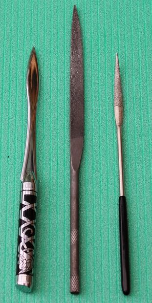
Step 15: Tools used
Tools Used
Letter opener is useful for gently removing prints from print bed.
Flat file for cleaning things up.
Small round one with point cleans out holes in the tabs that the pins need to freely insert into.
This post was originally on www.instructables.com created by user shadowwynd
Adapted Pen/Marker Holder
Many disabilities such as cerebral palsy make it hard to grip a pen, pencil, or marker. Some people can grab a pen in their fist and draw that way, but others lack the ability to keep their hand in a vertical configuration. This means that can only hold a pen sideways; hence they can not use it. This device is something we have used with several students. It adapts to hold pens, markers, pencils, and even small paint brushes. The student can then draw on paper.
These instructions will show a couple ways to make this, my preferred way (wood) and then a couple cheaper ways out of PVC for those with less money or tools.
Step 1: Supplies & Tools
supplies and Tools
Supplies (Preferred way):
1 x 36″ dowel (I often use 1″ or 7/8″, based on individual) (oak or pine, will make 5-6 holders) ($4)
Electrical tape or rubber tape Hurricane Nuts ($5 for 50) (or t-nuts with the smaller holes for screws)
1″ Plastic headed thumbscrews (# 91185A554 @ Mcmaster-Carr) ($7.49 for 10)
Glue (Gorilla glue, E6000, etc.)
Spade bits
Sandpaper
Steel wire
Supplies (cheap way #1):
1/2″ , 3/4″, or 1″ PVC pipe
“T” connectors
1/4-20 1″ bolt or 1/4-20 1″ Thumbscrew
Electrical tape
Supplies (cheap way #2):
1/2″ , 3/4″, or 1″ PVC pipe
“T” connectors
1/4-20 wingnut
1/4-20 1″ bolt or 1/4-20 1″ Thumbscrew
Electrical tape
Duct Tape
Tools: (Cheap way #1)
PVC cutter or saw
1/4-20 screw tap
Drill
Tools: (Cheap way #2)
PVC cutter or saw
Dremel or File
Drill
Step 2: Cut wood to size, shape
Cut wood to size, shape
Cut the dowels into 6″ or so lengths for adults. Children need about 4.5″, some adults prefer a smaller one that can fit in a hand, some want a longer one, etc. You can always cut a longer one shorter if the need arises. For teenagers upwards, I often make a combination of 6″ and 6.5″.
A table saw or chop saw is good for this step; lacking those tools I used a handsaw.
Using the sander, bevel one end of each cylinder so that it is rounded / domelike. This end may be in someone’s hand, so no corners or sharp edges. Slightly bevel the other end enough to remove sharp edges.
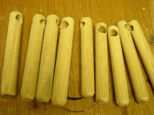
Step 3: Drill hole for marker / pen
Drill hole for marker / pen
I used a spade bit in the drill press to bore a hole through each dowel. I used 3/4″ for the 1″ dowels, and 5/8″ for the 7/8″ dowels. You do need to leave enough wood on either side that you still have some structural integrity. Obviously, the larger hole can accommodate bigger markers (such as whiteboard markers). Too big and the wood breaks; too small and many pens won’t fit.
I normally make the outer radius of the hole about 1/4″ from the end of the cylinder.
Using the drum sander, I bevel each side of the hole to remove rough edges.
Sand all sides with sandpaper to remove any splinters.
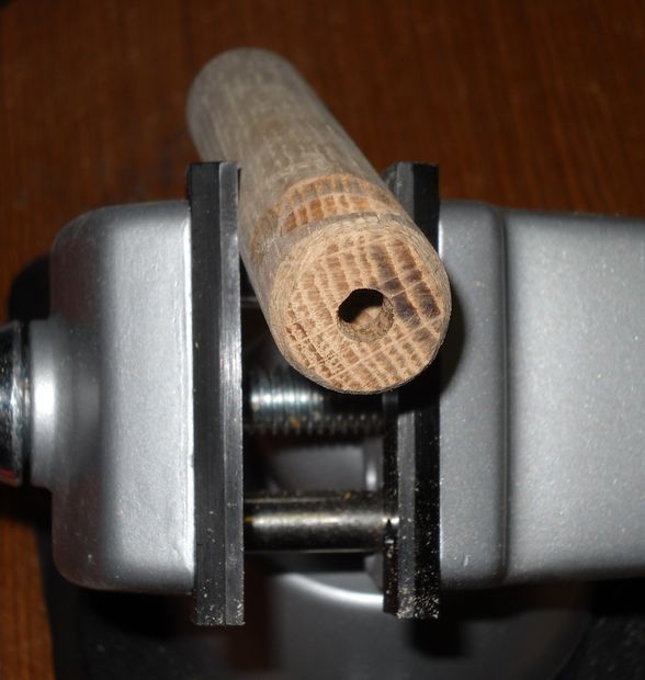
Step 4: Drill hole for nut
Drill hole for nut
Drill a hole through the end of each dowel (on the axis of the dowel, in the center, on the end closest to the big hole). This is for the T-nuts / insert nuts / hurricane nuts. It often helps to predrill a pilot hole.
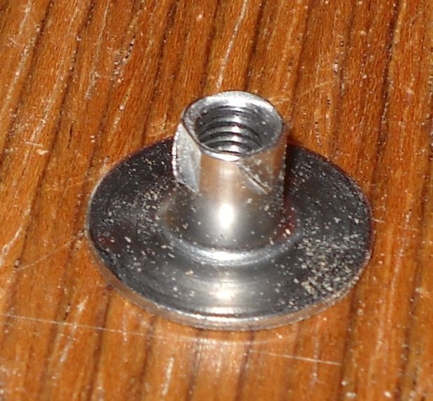
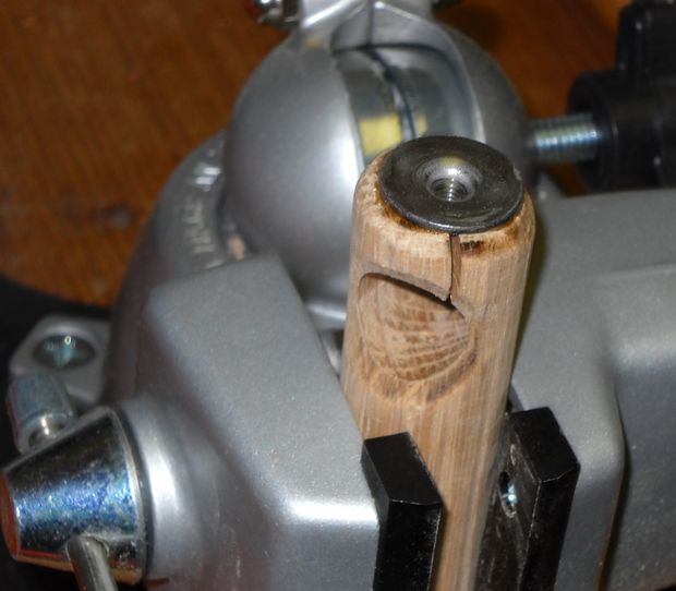
Step 5: Add hurricane nuts
Add hurricane nuts
Smear glue on the hurricane nut, then tap the shaft of the nut into the hole with a hammer.
The force from the thumbscrew is directed outwards.
The proper nut to use in this case is the insert nut. I don’t have good luck with these and end up destroying most of them trying to get them in. In this design, we also don’t have much wiggle room and the insert nuts take up more space, which then requires a longer thumbscrew.
T-nuts are intended to be used the other direction – the load pulls against the threads, which pushes the flange against the material. They aren’t designed to be pushed against. A hammer-in style T-nut will pop right out again when the thumbscrew is tightened. I sometimes use the T-nuts that are screwed in to the material using little bitty screws (like these), but the little bitty screws are easy to lose in a shop, are hard to drive, sometimes pop out of holes if predrilled, etc. The hurricane nuts seem to hold very well.
The problem with the hurricane nuts is that they tend to split the wood. So far I have had pine, oak, and poplar split on me. Sometimes the thicker 1″ cylinders arrive OK, but the smaller pieces split every time.
To remedy this, I cut a small channel around the top with the dremel. I put a couple of loops of steel wire in the channel, then twist it with pliers or use the ClampTite tool to tighten the loops. This prevents further expansion of the wood.
Sand everything.
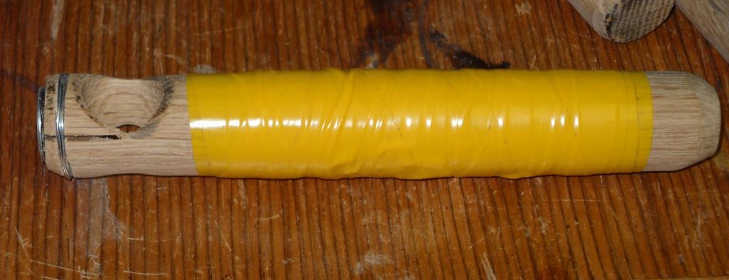
Step 6: Grip and Thumbscrew
grip
Wrap electrical tape or rubber tape. This gives it a grip that is easier to hold than slick wood.
Insert the thumbscrew into the hurricane nut. For these, I distinguish dowel sizes by thumbscrew color.
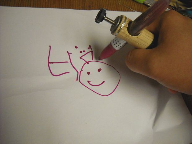
Step 7: Usage
Using it
Put a pen/marker in the large hole, tighten the thumbscrew to secure it.
This post was originally on www.instructables.com created by user TCFDATDept
Without stabilizer
Lap Desk Stabilizing Pad
A stabilizer is added to a commercially available lap tray to provide a stable work surface and encourage upright posture. For individuals with disabilities it is often difficult to sit on a couch or in a recliner and read a book or magazine or write. With the lap desk stabilizing pad, the user sits on a piece of material with 4 buckles attached. The lap desk is buckled to the material to prevent the tray from tipping.
Advantages
Portable
Stable – does not tip over
Improved upright positioning
Step 1: Materials
1 Lap Tray (sample styles shown)
· 1 Bottom Piece: 24” x 12” rugged material (denim or upholstery)
· 4 – 3/4” fastex buckles
· 8 pieces of 3/4” strap material cut to 7” lengths
· 4 – # 1/4-20 x 1” machine screws with lock nuts (length may change based on the lap tray purchased)
· 8 washers
· 4 – #10 lock nuts
NOTE: This was fabricated for an average adult. Size of the bottom piece may need to be modified to accommodate smaller or larger individuals.
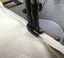
Step 2: Sew a hem around the bottom piece
Sew Hem
Sew a hem around the bottom piece to keep it from fraying. Iron on tape could also be used as a substitute.
Step 3: Prepare strap material
Melt the edges of the strap material with a heat source (heat gun preferred) to prevent fraying. Take 4 of the pieces, fold them in half, and thread through one side of the fastex buckle (doesn’t matter which side as long as they are all the same)
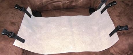
Step 4: Sew the straps to the material
Sew the straps to the material
Sew the 4 pieces from step 4 to the material.
Step 5: Preparing remaining straps
Take the remaining 4 straps, fold in half, and thread through the other half of the fastex buckle . Make a hole in the strap material for the bolt to go through.
Step 6: Attach straps to lap table
Drill a hole in each corner of the lap tray where you would like to attach the straps. Location should coincide with the location of the matching side of the buckle on the bottom piece. Attach the straps from to the tray using the 1/4” machine screws, washers, and nuts.
Step 7: Instructions for use
1. Set the bottom piece on the seat surface of the recliner, couch, or chair.
2. Have the user sit on the material. Be sure the material is not bunched or they are not seated on a buckle.
3. Place the tray over the user’s lap
4. Snap the buckles together to hold the tray in place