This post was originally on www.instructables.com created by user DarkRubyMoon

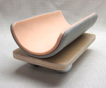
Footplate pads and bumbers
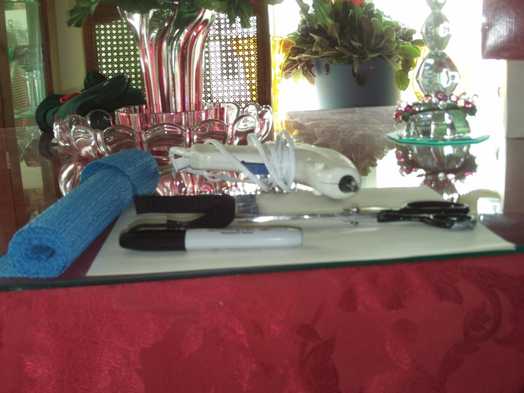
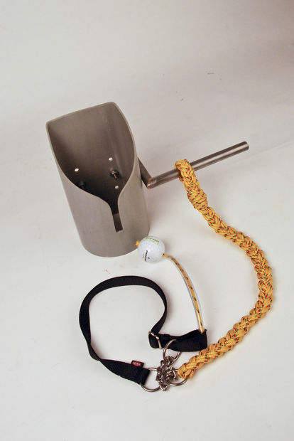
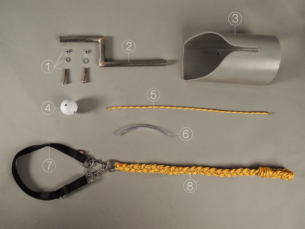
Materials Needed

Materials needed
Introduction
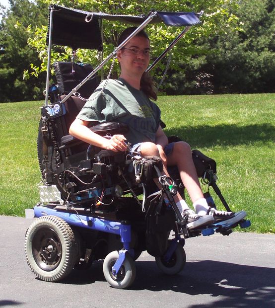
This is actually a double instructable on how to improve a typical wheelchair footrest by adding footpads and bumpers. The typical wheelchair footrest consist of either two rectangular pieces of metal or hard plastic to hold a person’s foot off the ground. They almost never have any sort of padding, and are strictly utilitarian. If you’ve ever had the experience of being picked up by someone to be sat into a wheelchair, the first thing one will realize is just how hard plastic or metal can be as one’s feet drop hard onto the footrest. Caregivers are usually careful to ensure one’s seat lands on the seat of the wheelchair, but they will just drop the feet once the person’s seat has landed. This can cause bruises on the feet, which with the compromised circulation in the feet of an individual with a disability can be quite serious. Slippers are usually a must, first thing in the morning as wheelchair footrest, especially metal ones, are very cold for bare feet, but they will often fall off one’s feet when being sat into a chair.
Another common problem with wheelchair footrest is that the corners of the footrest are often quite sharp. As modern power wheelchair’s are quite powerful, I’ve had the experience of actually tearing a large hole right through a dry-wall when one of the corners of my footrest hit the wall while I was attempting to make a turn. Feet are given little protection, and I’ve sprained and injured my feet as a result of hitting the walls with my feet as the feet extend beyond the footrest. In addition, for quite some time, we had a number of walls with large scratches resulting from the footrest clipping the walls in areas where the wheelchair has had to make sharp turns to get through the narrow halls of our house.
To solve these problems, I’ve added footpads to my footrest that both cushion my feet when I am placed in the chair and protect my feet from the cold. I have also added bumpers to the corners of the footrest that offer some protection to my feet as well as prevent scratches to walls and furniture.
The first half of this instructable is the footpads, the second half is the bumpers.
For the footpads, you will need the following materials:
- 1 roll of rubber shelf liner mat (available at most dollar stores in a variety of colors)
- Hook and Loop or Velcro brand fasteners with and without sticky back
- Scissors
- Paper
- Marker (permanent or sharpie brand)
- Hot glue gun and glue
- Optional Needle and thread
For the footrest bumpers you will need:
- 2 wheels off of an old pair of rollerskates or skateboard (Can find very cheap at flea market or yard sale)
- Spray paint (optional)
- 2 bolts
- 2 nuts for bolts
- 4 washers
- Drill gun
Step 1: Footpad design

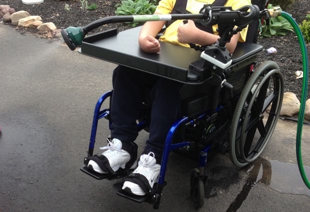
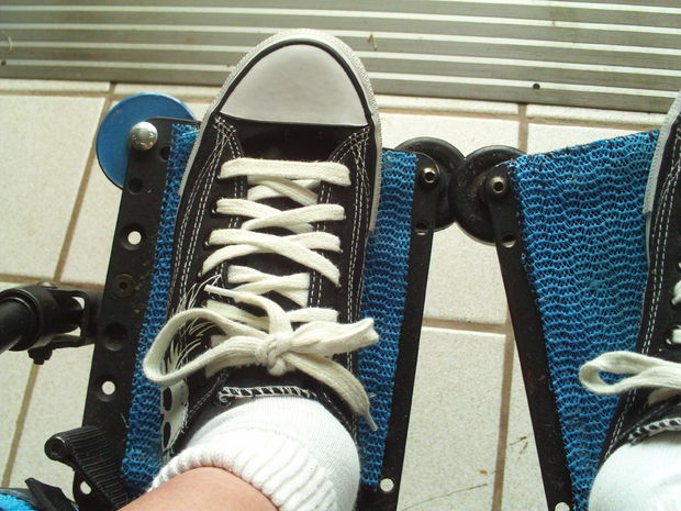
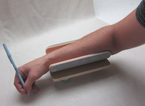
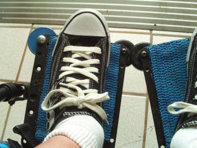
Footplate pads and bumpers in use
This foot pad design is actually my third version after two failed attempts. My first attempt at making footpads for my wheelchair, I simply cut two flat pieces of rubber and attempted to use spray glue to affix the pads to the footrest. This worked well for about one week. Just as footrest get very cold overnight, in the sun, they can get extremely hot. My particular footrest (a brilliant design for sure) are made of black metal that conducts heat like a frying pan. So, after one day in the sun, the glue melted and the rubber mat would not stick to the footrest. Instead, dirt and dust stuck to the glue on the footrest making quite a mess. I had to remove the footpads and the glue using alcohol to get rid of the sticky residue.
My second footpad design was very similar to this current version. I used one layer of the rubber shelf liner, cut it to the size of my footrest, then used sticky back hook and loop (Velcro) to attach it to the footrest. This worked well for two weeks. The sticky glue on the hook and loop stuck to the footrest fine, but it pealed off the rubber shelf liner.
This final version I have been using now for several months. It is made with the idea that it will wear out eventually. It still uses hook and loop fasteners (velcro) to attach to the footrest so that it can be easily removed.
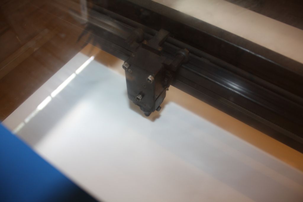
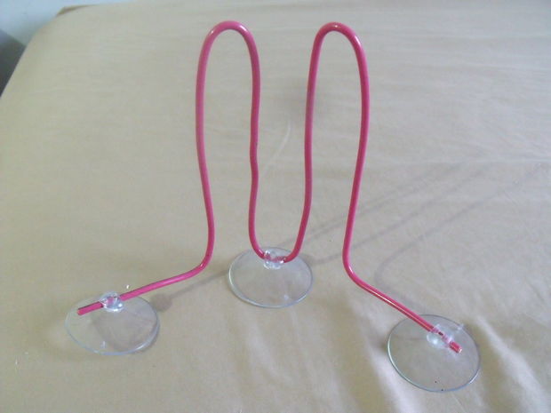
Step 2: Foot-pad Template

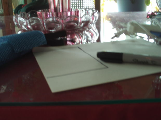
Creating the footplate template
The first step is to determine what size and shape you want to make your foot-pad for the footrest of your wheelchair. The best way to do this is to place a sheet of paper onto the footrest and draw the shape that you want to make your foot-pad. Cut out the shape and sit it onto the footrest to make sure it fits onto the footrest of the chair and that it is large enough to accommodate your foot.
Step 3: foot-pad Tracing template
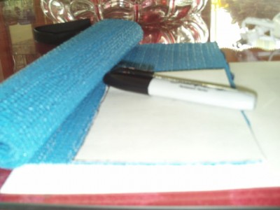
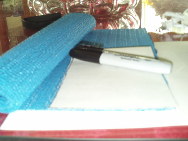
Tracing the foot-pad template
Once you have a template for your foot-pad, trace the template onto your rubber shelf liner. The rubber shelf liner is commonly available at most Dollar stores and other large retail stores. It is basically a porous thin sheet of rubber that comes in a variety of colors. Pick a color that matches your wheelchair for best appearance. My particular wheelchair is blue, so I picked a light blue shelf-liner.
Trace the paper template onto the rubber sheet using a permanent marker (like a Sharpie). You will want to trace this shape four times, twice for each footrest. Keep in mind, you will be making one for the right foot rest and the left. My particular foot-pad is rectangular, but if you make yours in a different shape, the right and left should mirror (be opposite) of one another. If you need to mirror your shape, trace your template twice on one side, then flip it over and trace the template two more time
Step 4: foot-pad Cut template from shelf-liner
Cut out the template from your shelf-liner using the marker lines to guide your cuts. After you cut out your foot pads, you may want to sit them on the footrest to make sure they fit the way you want them to. If they do not, make any trims as necessary making sure to make the same cuts for each of the pads you cut from the liner.
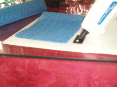
Step 5: foot-pad Gluing pads together
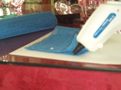
Gluing pads together
For my foot-pads, because the shelf liner is so thin, I decided to double it by gluing two pieces together. For each foot pad, take the two matching pads. You will want to put the sides that have the marker lines such that they are facing one another so that they will not be visible once glued. Before using the hot glue gun, place cardboard or something under your work area so that you do not get glue on your table surface.
The rubber shelf-liner is very porous, so you have to be extremely careful gluing the two pieces together. Also, the rubber of the liner itself tends to melt slightly from the heat of the glue gun. Very carefully put small drops of glue all around the outter edge of the two pads so they stick together as a single foot pad. This will give them much more cushioning then if used as a single layer. Watch your fingers as you stick the pieces together as some of the hot glue will seep through the pads. Be careful not to glue the pads to your work table.
Let the glue of the pads dry for a few minutes. Once the glue dries some, you can remove any excess glue.
Step 6:foot-pad Hook and Loop
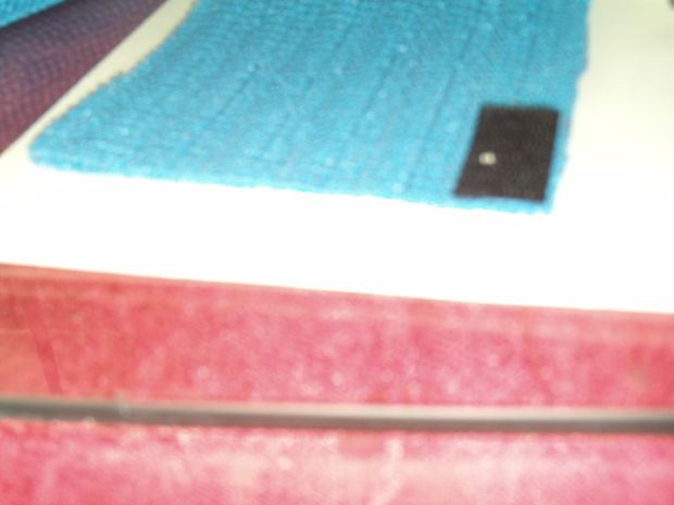
Gluing on hook and loop

Hook and loop in place
he reason for using Hook and Loop fasteners to attach these foot-pads is that they will eventually wear out and need to be removed and replaced. The wear of putting your foot on the pads and spilling stuff on them will eventually require that they be replaced. Also, in my initial attempt at gluing the pads to the footrest, I discovered that ordinary spray glue will not hold the foot-pads on.
Hoop and Loop fasteners come in both sticky back and non-sticky back varieties. I recommend using sticky back Loop fasteners (the soft side) to stick onto the footrest and using the non-sticky back fasters to glue onto the rubber foot-pads. If you choose to use the sticky back fasters on the rubber foot-pads, it will work for a week or two, and then come un-glued.
Take a strip of the non-sticky back hook fastener (the rough plastic side of Velcro) and cut it into several small strips, at least one for each corner of the foot-pad. Using your hot glue gun, carefully glue the fastener onto each of the corners of the rubber pad using a generous amount of glue. Once again, be very careful as the rubber mat is very porous and some glue will seep through and could burn your fingers. Press the faster firmly onto each of the corners and allow to dry. Be careful to not glue the pads to the table your working on. I frequently lifted the pad off of a cardboard work surface to make sure that the pad was not sticking to the cardboard. Allow to thoroughly dry.
Cut matching length strips of sticky-back loop fasters (the soft side of velcro). Line these up with the foot-pad’s hook fasteners by putting them together with the stick-back up. Peal off the protective cover of the sticky side, and carefully stick the foot-pads onto the footrest in their desired location.
Your foot-pads are done! Now your feet can land on these nicely cushioned pads that protect your feet not only from hard landings onto your wheelchair, but also protect your feet from the hot and cold of the footrest. Now I don’t need slippers on anymore when I am sitting in my chair, and don’t have to worry about my feet banging hard onto the metal footrest.
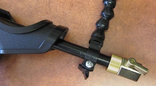
Step 7: BUMPERS
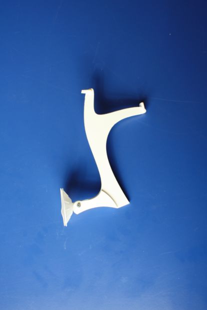
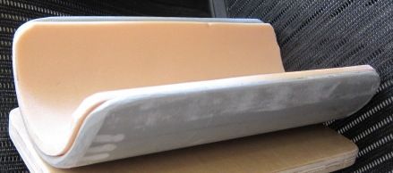
Footplate Bumpers
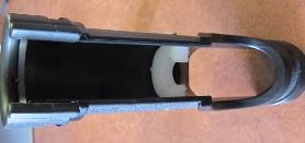
The bumpers I designed for my footrest were actually an improvement on what the manufacture had done to my footrest. This chair came with tiny wheels on the corners of each of my footrest to protect walls and things from scratches do to the sharp edge of the footrest. Most footrest do not come with these. The wheels on this footrest were very tiny and did not offer much if any protection.
I decided to replace the tiny wheels in the corner of the footrest with much larger roller-skate wheels. These larger wheels, in addition to offering more protection to my feet and the walls also looked much nicer on the chair.
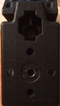
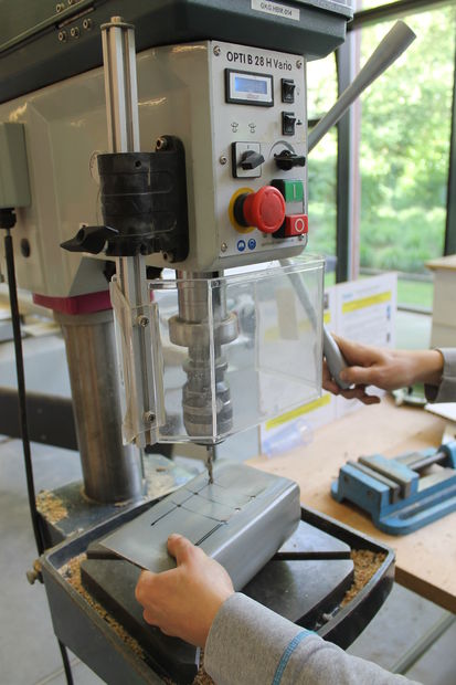
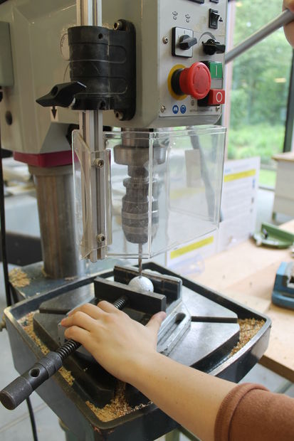
Step 8: Bumpers � Drill if necessary
As I was merely replacing existing wheels on my footrest, the footrest already had pre-drilled holes. If this is not the case with your wheelchair, you will need to drill two holes, one on the far right corner of the right footrest, and one on the far left corner of the left footrest. This hole should be close to the edge, but should not compromise the structural integrity of the footrest. Be sure to check with your wheelchair’s warranty before making any permanent modifications.
Step 9: Bumpers roller skates baby!

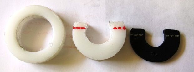
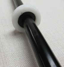
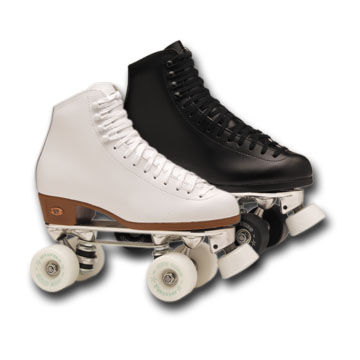
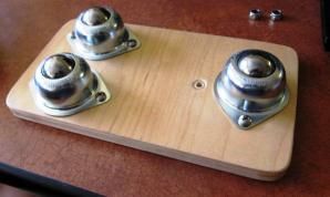
Rollerblade Wheels
Remove the wheels from an old pair of roller skates or even an old skateboard. For my wheels, I purchased an old worn out pair of children’s roller-skates at a flea market. You only need two wheels, so I saved the extra wheels as spares. As the wheels of these old skates were a bit worn and an ugly grey, I used blue spray paint to color the wheels a pretty blue to match my chair. This is optional.
Step 10: Bumper -Bolt
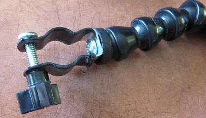
The bolt you select for holding the wheels on is very important. You want a bolt with a fairly flat head as it will be sticking up some on the footrest, and you don’t want your foot slamming into a metal bolt every time you are seated into a wheelchair. The bolt needs to be long enough to go through the footrest and the skate wheel such that it can be secured with a nut. The bolt also needs to fit in the footrest drilled hole.
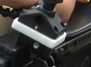
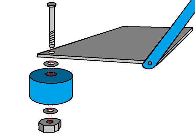
Step 11: Bumper attach
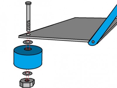
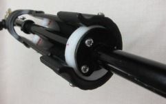
Attaching bumper wheel
Attach the bumper wheel to the footrest using the bolt. Put washers between the wheel and the footrest and between the wheel and the nut to allow it to spin freely. Note: You may on occasion have to tighten the bolt as it will eventually work loose if the bumpers spin frequently from bumping into things. Normally, the wheels don’t move, so the bolt does not loosen.
Step 12: Bumper safety and use
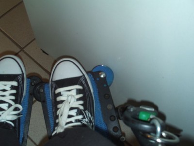
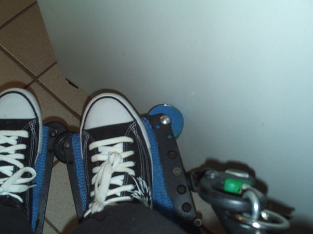
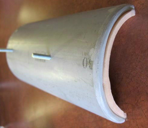
Finished bumper wheels
This bumper is a bit like a spare parachute for a sky-diver. It is good to have, but you should hope never to use it. I’ve run into a few walls since attaching these wheels. What the bumper tends to do is if you hit a wall at an angle, most times it pushes the front end of the chair over without leaving marks on walls. It offers some protection to the feet in a direct hit of a wall, but not much. Primarily, these bumpers will protect what your hitting, and not you… but at the same time, they offer enough protection that I personally think they ought to be standard equipment on all wheelchairs.